Just as you don’t pull the mask off that old lone ranger and you definitely do not want to mess around with Jim, you don’t want to use a transformer* when an AC to DC adapter is called for. But how do you know exactly what you have without a spec. sheet? How do you know without a meter which wire of a DC output is negative and which is positive? You can check the tiny print on the adapter itself.
* Transformers are AC-in and AC-out devices that change the voltage. They can increase (step-up) or decrease (step-down). Wall wart transformers usually step-down the voltage.
Output Voltage, Amps (often mA – thousandths of an amp)
Most model railroaders keep every piece of junk they can find in hopes of finding a use on the layout. If you have a drawer full of wall warts chances are some are AC to DC adapters and some are AC to AC transformers. Both have use on the layout, but, are NOT INTERCHANGABLE in many instances (e.g. A tortoise requires DC). How can you tell if the nomenclature on the adapter does not include the “DC” designation? Look for this symbol:

This symbol along with the voltage and amperage specification will tell you if you have the correct adapter assuming you know the current draw of the powered device. In the example of a tortoise switch machine, Circuitron documentation states that each tortoise draws about 15-16 mA and that the voltage must not exceed 12V. So, if your adapter is labeled at 9VDC / 200mA, can you use it? YES! In fact you can power a dozen tortoises with this adapter. Nine volts will run the switch machine slower than if it were 12V. (This is both quieter and a more prototypical movement of the turnout points.)
Does this mean that if you only have a 120 volt to 12 volt transformer that you are out of luck? Not necessarily as you can use a transformer if you use a pair of diodes to “steer” the current. If this is your scenario, refer to the Tortoise documentation.
Polarity Symbols – Barrel Plugs
Most wall wart adapters have a plug on the other end of the wire pair that is attached to the wallplug-mounted unit. The plugs exterior surface is connected to one wire and the center/tip is connected to the other. If the adapter is a transformer (AC output), it will not matter which way it is connected.
For DC, however, since there is no standard for plug polarity, the following symbols are used to denote which wire is positive and which is negative:
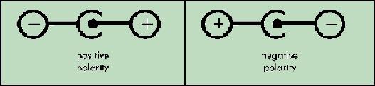
The symbol connected to the dot (usually the symbol found to the right) denotes the polarity of the center/tip, whereas the symbol connected to the broken circle denotes the polarity of the barrel/ring. When a device or adapter is described simply as having “positive polarity” or “negative polarity”, this denotes the polarity of the center/tip.
Class Symbol
Adapters often are constructed with two-pronged plugs rather than including a third (ground) prong. These adapters should have the following symbol:

This denotes that the adapter is Class 2 which infers that it is double-insulated and does not require a ground connection. Class 1 devices would not have this symbol, would require a gound connection and should have the third prong. This should not have any effect for model railroad use, but, just in case the info is there. And one final word: don’t tug on Superman’s cape.
